When you watch a movie, you've probably noticed those black bars along the top and bottom of the image. Movies are produced in various "aspect ratios" (the ratio of the width:height of the image). Some movies are produced in 16:9 aspect ratio. If you watch these movies on an older non-HD television (which has a 4:3 aspect ratio), then you will get black bars above and below the image. If you have a newer HDTV with a native 16:9 "wide screen" then you won't get any black bars since the aspect ratio of the HDTV matches the aspect ratio of the movie. However, some movies are produced in 2.35:1 "Cinema Scope" format. When watching a 2.35:1 movie, even on your widescreen HDTV, you will still get black bars on the top and bottom of the image.
Currently, there are no televisions or projectors that have a native 2.35:1 aspect ratio. But there are several ways to remove these black bars to get the full Home Cinema Scope experience.
First, of course, you need a 2.35:1 aspect ratio screen. You can buy screens in this aspect ratio, or make one yourself. Some people just paint a large wall or piece of material that hangs on the wall. In my case, I stretched "black out" fabric over a large screen-door frame. You can buy the metal strips that go around the edge of a screen-door at the hardware store. Just mount these strips to a large sheet of plywood, then stretch the black-out fabric just as if it were screen-door mesh. It makes a great screen.
Once you have a wide enough screen, the easiest way to eliminate the black bars is to zoom your projector so that the black bars are projected above the top of the screen and below the bottom of the screen. Essentially, you just zoom out until the width of the image fills the width of your screen. If you have a dark-colored wall, or cover it with black felt, then you'll never notice the light-spill over the top and bottom of the screen.
I used this method for years and it worked fine. The problems with this method is that you are enlarging the entire image, making the pixels larger, and are wasting the brightness and resolution from the black bars which are still being projected above and below your screen. Also, newer projectors often cannot zoom an image enough to fill the screen, and might also require lens shift adjusting to center the image vertically on your screen.
The solution to this, and the best way to achieve Home Cinema Scope, is using a special lens in front of the projector called an "Anamorphic Lens". An "Anamorphic Lens" will stretch (or compress) an image in one dimension (vertically or horizontally). Most projectors have a "zoom mode" that stretches the image vertically and eliminates the black bars. Rather than projecting "black" and wasting those pixels, all vertical pixels are used for the movie image itself. This vertical stretch will cause people and objects on the screen to look tall and skinny. However, once the projector is displaying the full image vertically, you can then use an Anamorphic Lens to stretch the image horizontally to restore the correct aspect ratio.
That's a lot of words! Let's look at some pictures to understand this better:
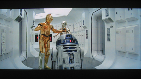
This is what you are probably used to seeing on your HDTV. Those annoying black bars on the top and bottom. Now let's project this onto a 2.35:1 screen:
(click for larger image)
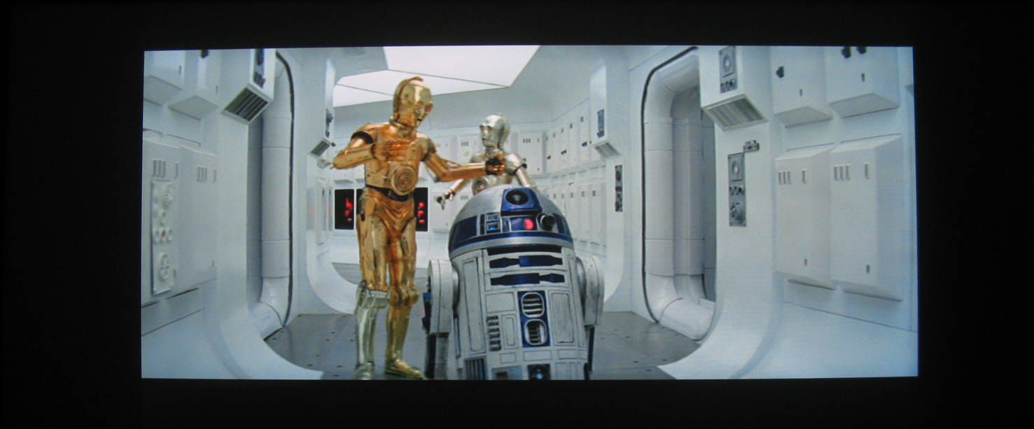
Yes, I can hear you already: "This is even worse!" Now you have black bars on the top and bottom AND on the left and right! Patience...this is just the beginning. Now, let's activate the projector mode that stretches the image to fill the entire vertical height of the screen. On my Infocus Screenplay 7205 projector, this mode is called "Letterbox":
(click for larger image)
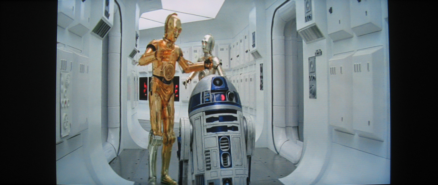
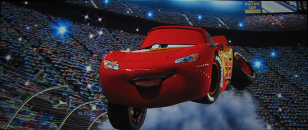
This stretch is just coming from the projector's "Letterbox" mode. No lens is used yet. Notice that C3PO and R2D2 look stretched (tall and skinny). This is what the lens will fix. When an Anamorphic Lens is placed in front of the projector, we get this final image:

(click for larger image)
Now that's looking nice! No black bars at all. And since the full vertical resolution of the projector is being used, the image remains nice and bright and sharp. Static images really only provide part of the story. I can't convey the emotional immersion that results in watching the full Cinema Scope image rather than the first image that only utilized the middle of the screen. It feels like the same difference between watching a movie on TV vs watching it in the theater.
Of course, the downside to using a 2.35:1 screen is that when you watch 16:9 format material (or regular 4:3 format television), then you have black bars on the left and right of the image instead of the top and bottom. This kind of setup is called a "Constant Image Height" (CIH) because the height of the image remains the same no matter what you are watching. This is exactly how normal movie theaters work. The image is always the same height, but the theater has retractable curtains on the left and right side of the screen that they can use to adjust the width of the screen depending upon the aspect ratio of the movie being shown. You can add curtains to your own home theater to provide the same feature. In my case, I just live with the black bars on the left and right. But masking the left and right bars with curtains is much easier than masking the top and bottom black bars in a normal HDTV setup.
Most people who want a Home Cinema Scope setup simply purchase a commercial Anamorphic Lens, or purchase a high-end projector that already has such a lens attached. But these lenses typically cost over $1000. You might think that it would be very difficult to make your own Anamorphic Lens. You'll be surprised to learn that making your own Anamorphic Lens is actually a very easy DIY project (even easier than making your own 2.35:1 screen).
 The
secret is "prisms". If you remember back to your high
school science class, a prism is often used to split a beam of light into a
rainbow (think of the cover of the "Dark Side of the Moon" by Pink
Floyd). Whenever a beam of light hits a surface, some light is reflected, and
some light is "refracted" (or bent). Notice that as the beam of white light
hits the surface of the prism, each color is refracted (bent) a different amount.
Then, when each color hits the second edge of the prism (on the right), each
color is bent even more.
The
secret is "prisms". If you remember back to your high
school science class, a prism is often used to split a beam of light into a
rainbow (think of the cover of the "Dark Side of the Moon" by Pink
Floyd). Whenever a beam of light hits a surface, some light is reflected, and
some light is "refracted" (or bent). Notice that as the beam of white light
hits the surface of the prism, each color is refracted (bent) a different amount.
Then, when each color hits the second edge of the prism (on the right), each
color is bent even more.
Now, imagine putting two prisms next to each other, but reversed so that the second prism takes the rainbow from the first prism and converts it back into a white beam of light. With two prisms, you put a white beam in, and you get a white beam out. But by adjusting the angles of the prisms relative to each other, you can bend the outgoing beam of light and essentially magnify it. This is exactly how an Anamorphic Lens works!
There is a wonderful web site that uses a Java Applet to demonstrate how prisms work: NTNUJAVA Virtual Physics Prism site
There are several ways to get a prism the size that you need. Many people have made their own prisms by cutting glass to make the surfaces, then seal the glass together to make a hollow prism, and then fill it with water or mineral oil. You can make very large prisms in this way. However, most home theater owners don't like the idea of potentially leaking prisms hanging from the ceiling in front of their projector. Sealing these glass prisms so that they do not leak over a long period of time can be difficult.
 Fortunately,
an inexpensive solution is available. Several companies
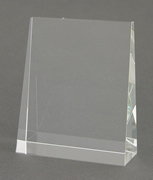
now manufacture crystal "award" plaques. These crystal plaques
are meant to be engraved with some award and then sit on your desk or a shelf. They
are wedge-shaped, with the base of the plaque larger than the top of the plaque. If
you look at the side profile of these crystal wedges, they match the picture
of the prisms shown above. They come in several sizes, such as 4"x6" (measuring
the front face that you would normally have engraved) up to 6"x7.5".
Fortunately,
an inexpensive solution is available. Several companies
now manufacture crystal "award" plaques. These crystal plaques
are meant to be engraved with some award and then sit on your desk or a shelf. They
are wedge-shaped, with the base of the plaque larger than the top of the plaque. If
you look at the side profile of these crystal wedges, they match the picture
of the prisms shown above. They come in several sizes, such as 4"x6" (measuring
the front face that you would normally have engraved) up to 6"x7.5".
There are several sources for these prisms. In the U.S., I have used Massillon Plaque. In Australia you can use EvRight. If you call your local award plaque company, they can probably point you to other sources. At the time that I purchased the small prisms, they were about $29 each (without engraving). Be sure to call the company to find out if blank wedges are available. Also, the blank wedges are usually cheaper than the prices listed on the web site, since they don't need to charge you for any engraving.
These are not plastic or acrylic. They are very heavy, crystal glass. I don't think they are "lead crystal", but are some modern variation. I've even heard some people say that it's the same stuff they make spacecraft windows out of. What's important is that they are optically very clear and the surfaces are very flat and uniform. It's important to get two identical prisms, since the second prism needs to cancel the rainbow created by the first prism. If there are differences in the prism angles, or if the surfaces are not perfectly flat, then you will get more "chromatic aberration" (which will look like blurring at the edges of the screen).
If you are planning to build your own Anamorphic Lens, I recommend that you just purchase a couple of prisms and then start playing with them. It's impossible to provide exact construction dimensions and angles because each projector setup will be slightly different. The angle between the two prisms will depend upon the throw distance of your projector, and the size of your screen. So, if possible, just put your projector on a table and place the prisms in front of the projector. Then start playing with the angles. In my case, I placed the prisms on a piece of paper, and when I had the prisms adjusted, I just traced the outline of the prisms onto the paper as a template for construction (more on that later).
Just set up the prisms in roughly the configuration shown in the 2-prism diagram above. As you adjust the angle of the first prism, you will be adjusting the right-edge of the image on the screen. As you adjust the angle of the second prism, you will be adjusting the left-edge of the screen. I placed some tape on my screen (the blue painters tape that doesn't leave any marks or residue) and make marks for the proper 2.35:1 size. Then I just adjusted the prism angles until the image expanded to hit the marks.
In fact, it's so easy to set this up and align it, that it's even possible to use these prisms for temporary setups where you just put the projector on the coffee table, then place the prisms in front of it. It's not perfect, but it works easier than you might think. But after a few minutes of playing with the prisms you will get the hang of it. The initial results are so impressive, that you might be tempted to just start watching movies already! Trust me...you'll want to watch your entire collection of 2.35:1 movies all over again!
Playing with the prisms on the coffee table is fun. But eventually you are going to want to mount these prisms in some type of enclosure that you can place in front of your projector. In my case, my projector hangs from the ceiling. So I needed an enclosure that could also hang from the ceiling. The type of enclosure that you need will really depend a lot on where you have your projector mounted already.
Because we are building a "horizontal stretch" lens, you do not need to move your current projector. Some people like to make a "vertical compression" lens (which you can also make using two prisms) and then move the projector so that it projects the full width of the 2.35:1 image, and then use the lens to compress the image vertically to fit on the screen. Some people feel that you get a better quality image using vertical compression, but I didn't want to move my existing projector location, and I also wanted a way to move the lens out of the way when I'm not watching 2.35:1 movies.
Enclosures can be built out of a variety of materials. The most common materials seem to be either aluminum or wood, depending upon your preference (and what tools you have available). I made my own enclosure out of 1/2" MDF because it is cheap and easy to work with. My design was based upon the original "Aussiemorphic Lens" from Mark Techer. His blog provided my initial inspiration. Ideas from many people in the DIYAudio.com forum were also used. In particular, I wanted to be able to easily adjust the prism angles once they were inside the enclosure for fine tuning then lens.
 To
start, I needed to attach bolts to the top and bottom of the prism which would
be used as rotation points. Just gluing a flat-head bolt to the
prism doesn't work very well. However, if you first cut a triangle of
plexiglas (or other material...some have just used cardboard), then you can
drill a hole in the plexiglas, countersink it for the screw head, then place
the screw between the prism and the plexiglas and epoxy the entire piece of
plexiglas to the prism.
To
start, I needed to attach bolts to the top and bottom of the prism which would
be used as rotation points. Just gluing a flat-head bolt to the
prism doesn't work very well. However, if you first cut a triangle of
plexiglas (or other material...some have just used cardboard), then you can
drill a hole in the plexiglas, countersink it for the screw head, then place
the screw between the prism and the plexiglas and epoxy the entire piece of
plexiglas to the prism.
Remember that the "top and bottom" that we are gluing screws to are really the left and right edges as shown in the picture of the award plaque sitting on a desk. When placed in front of the projector beam, these become the top and bottom edges within the enclosure. The screws fit into holes in the top and bottom of the enclosure with wing nuts. Loosening the nuts allow the prisms to be rotated to adjust the alignment.
It is also very important to mask the sides of the prisms. As I mentioned earlier, whenever a beam of light hits a surface, part is refracted (bent), but part is reflected. With these glass prisms, a reflection from one surface is only about 4% of the main beam intensity. A double-reflection is only about 0.1% of the main beam intensity. However, in a dark theater, even a 0.1% reflection is visible on the screen. Most of these reflections exit from the two ends of the prisms. I just used black electrical tape to mask the ends.
Once each prism has a bolt plate glued to the top and bottom, then it's time to make the enclosure itself.
The enclosure is shown from the top (upper-left picture), with the projector at the top and the screen towards the bottom. The bottom-left diagram is looking from the screen towards the projector through the box. The enclosure really is a fairly simple 4-sided box. As shown in the bottom-left view, the top is screwed to the sides, while the bottom is glued and held to the sides using splines (or biscuits if you have a biscuit-joiner). I tried to minimize screws and only use them where it was necessary, since the top needs to be removed to change or clean the prisms. But MDF doesn't hold screws very well, so biscuit joints and glue work best.
The top view also shows the tentative position of the prisms (looking down on the prisms). The circles represent the screws that were glued to the top and bottom of the prisms. The inside of the enclosure is lined with black felt that is glued to the MDF using a spray adhesive (rubber cement also works well).
Once the enclosure is built, then you need to decide how to mount it in front of your projector. In my case, my projector is flush mounted with the ceiling. Since I wanted to be able to remove the lens from the front of the projector, I designed a "sled" which attaches to the ceiling via two drawer slides. The sled itself is just another piece of MDF, painted white to match the ceiling. To attach the enclosure box to the sled, I made a U-shaped bracket using oak. This bracket needs to be stronger than MDF, so a hardwood like oak or maple would work well. An aluminum bracket would also work well. The bracket is slotted to allow adjustment on the sled, and also adjustment to the enclosure.
OK, time for some real pictures of the actual enclosure mounted on the ceiling. I apologize for not having any pictures during the actual construction...I didn't have my camera yet.

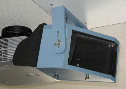
The side image shows an extra bit of felt glued to the back of the enclosure near the projector. This prevents some of the reflections generated by the prisms from getting out and reduces the light spill onto the walls. An additional piece of felt is actually glued to the back of the box with just a circular cutout for the projector lens. You can see the wing nuts on the bottom of the enclosure box that are used to adjust the prism angles. You can also see the wing nuts on the side which are used to attach the bracket to the box, and the slots where the bracket is bolted to the white sled. If you look closely, you can see the plexiglas that is epoxied to the top of the prism. You can also see the black electrical tape that covers the wide end of the prism (on the right side of the prism in the first image).
Here is the enclosure moved to the side of the projector:
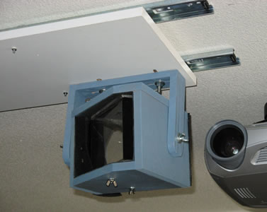
This gives a better view of the "sled" which is attached to the ceiling using two drawer slides. To move the lens out of the way, I simply push the entire lens assembly to the left. The ceiling is low enough that it is easy for me to just reach up to move the lens. If you had a higher ceiling, then you could attach a cord to the sled to drag it left or right. The drawer stops prevent the sled from being moved too far in one direction or the other. You can actually build the sled even better and can completely hide the drawer slides even when the lens is moved out of the way. I got my upside-down directions messed up, which is the only reason the drawer slides show. But at least it makes the picture easier to understand.
Notice that the bracket is designed to allow the lens box to tilt up and down. A slight tilt is needed to improve the geometry of the image. You will get pin cushioning in the corners of the image, and by tilting the entire lens you can minimize this geometry distortion and make it more uniform on the top and bottom of the image. I actually zoom my image out just a bit so that the pin cushioning is masked by the black felt around the outside edge of my screen.
When watching movies, you will be amazed at the performance of this lens. The last Star Wars image shown above is an actual picture using this lens. However, if you connect a computer to the projector and start playing with test images, then you will learn a bit more about the potential short-comings of this DIY lens. But before I discuss these details, I can't stress enough how minor they really are. It's easy to get depressed when looking at test images. The test images are useful to try and improve the design, but the overall result of watching movies is much more positive than you might think looking at the test images.
The first issue is the uniformity of the aspect ratio. Converting a 16:9 image to a 2.35:1 image requires a 133% stretch. However, if you put a grid onto the screen and actually measure the rectangles, you will discover that the rectangles in the center of the screen are 127%, and the rectangles on the right and left edges of the screen are 142%. The perfect 133% stretch only occurs in the left-center and right-center of the screen. It is uniform from top to bottom. It is only left-to-right that shows the aspect ration change.
Fortunately, the human eye is not sensitive to these kind of changes in aspect ratio. Even when moving an animated circle around the screen, it is very difficult to detect the aspect ratio changes to the circle as it moves left and right on the screen from the normal viewing distance (about 10 ft from the screen in my case, which is closer than most for a 124"x53" screen).
Also, according to reports from people who own commercial Anamorphic Lenses, the commercial lenses suffer from the same aspect ratio non-uniformity.
A larger problem is the color problems at the edges of the screen. As we know, the first prism is splitting the light beam into a rainbow. If the second prism can't precisely undo this, then you won't get a white beam on the screen. And in fact, it is impossible for a flat prism surface to perfectly correct the rainbow from the first prism because the light beam is actually a spherical wave and not a flat wave. So, as you move towards the right and left edges of the screen, the light beam starts to get split more into a rainbow. This gives a slightly colored edge to some objects. Here are some very close up pictures of the test grid in the middle of the screen, and then on the right edge of the screen:
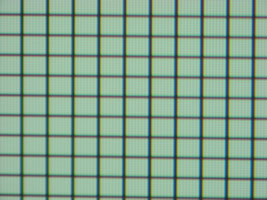
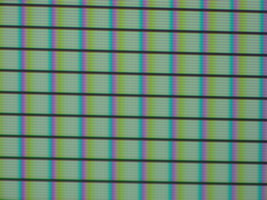
Notice how the horizontal lines are still perfectly black in both images. However, the vertical grid lines are black in the left image, but look like rainbows in the right image. If you look closely, you will see that the black line is blue and has a yellow edge on the right side of it. This makes the image look blurry. Notice that you can actually see the DLP pixel structure in these images, and that the rainbow is about two pixels wide. Now here is a full view of the same grid on the entire screen:

(click for larger image)
Note that the geometry pin cushioning and the change in brightness across the screen is caused by the digital camera and not the lens or projector. But you can still tell that the left-most and right-most parts of the screen are a bit blurrier than the center of the image.
This chromatic aberration can be reduced by using four prisms instead of two. You essentially "double" each prism by putting another prism next to it in the exact same orientation. Essentially you are making two prisms with a larger internal angle. This allows you to reduce the angles of the prisms relative to the light beam, resulting in less bending of the light. The less the light beam is bent, then the smaller the rainbow on the edges.
At normal viewing distance, the eye cannot really detect the rainbow itself. It's very hard to see any color edges on objects in movies. The only real effect of this problem is that it makes the image on the left-most and right-most parts of the screen slightly blurrier. While this is noticeable when using a computer image, it really isn't very noticeable during movies. However, this is certainly something to be improved in these lenses and something the commercial lenses do a better job of correcting.
As mentioned before, each time a beam of light hits a surface, it is both refracted (bent) and reflected. In a dark theater, these reflections can be quite visible and quite distracting if you don't do something to get rid of them. Fortunately, the majority of reflections are at angles that can be easily blocked by the enclosure. When you first play with the prisms without an enclosure, however, you will be able to see all of the different reflections around the side and back walls of your room.
Fortunately, all we need to worry about are reflections that end up on the front screen. As it turns out, there is a single reflection from the 2-prism lens that can appear on the front screen. This reflection occurs just as the beam of light is exiting the final surface of the final prism. The light reflects internally within the prism, then reflects again on the first surface of the same prism, resulting in a beam that hits the screen near the first beam. Fortunately, since this is a double-reflection, it's intensity is approximately 0.1% of the main beam intensity. Also, given the geometry of the lens shown in this article, only the right-most part of the image is reflected onto the left-most part of the screen. Given the low intensity, you can only see this reflection when there is a bright object on the right side of the screen and the left side of the screen is very dark. In some cases, you might see a dim reflection of credits at the end of some movies, since they are moving (making the reflection easier to detect) and are typically bright white letters on a black background. However, this reflection is so dim that I wasn't able to get a picture of it in my camera. And most movies do not show this reflection at all. The best test case I have for demonstrating the reflection is the very opening of the James Bond Goldeneye movie, where the white spot light moves from left to right (the trademark James Bond opening where the white spotlight turns red and then zooms into the actual first action scene). When the white spotlight is on the right-most part of the screen, you can see a dim reflection on the left side of the screen.
Using more prisms to reduce chromatic aberration unfortunately provides more surfaces to generate reflections. A 4-prism lens has several other reflections that can hit the screen. I find myself more sensitive to reflections and less sensitive to chromatic aberration, so I prefer the 2-prism lens. But you might want to play with four prisms to see what you think yourself.
Unfortunately, the only way to reduce this reflection is to coat the prisms with some sort of non-reflective coating, without effecting the optical clarity of the prism. Such coatings are very expensive and are something you can expect on commercial lenses, but difficult to achieve for DIYers.
I cannot stress enough how immersive a constant-image-height (CIH) theater can be. If you can remember your first thrill at having a large "movie theater" in your home, going to a 2.35:1 screen with CIH will give you that same thrill all over again. I had thought for the past five years that just zooming the projector was good enough (and it was certainly better than just a 16:9 screen). But using an Anamorphic Lens instead of just zooming the projector is simply an amazing difference in picture quality. When I tell people about CIH, I always warn them that it's almost a curse: once you have experienced a CIH theater, then you never want to go back to a simple HDTV or 16:9 screen again.
Fortunately, thanks to many DIYers, it is possible to construct your own Anamorphic Lens fairly easily and inexpensively. It has certainly been one of the most satisfying projects I have ever done for my theater. I'll leave you with an image that just seems to express my happiness with this lens.
I owe my thanks to many people who have contributed ideas to this project. Most of these people have contributed to the very long forum thread on the DIYAudio.com site. If you are serious about a DIY Anamorphic Lens, then you own yourself to spend the hours it will take to read this entire thread. Mostly I want to thank Mark Techer and his Aussiemorphic Lens blog, not to mention his many early posts about building water and oil prisms before the crystal wedges were discovered. Then I should thank Steve Scherrer for his discovery and post of the U.S. source for these prisms, and for his ideas on attaching screws to the prisms to make them adjustable. Also, thanks to dvarma who posted a PDF link to his description of an enclosure that used a drawer slide to attach it to the ceiling, which was an inspiration to my own enclosure bracket.
I wish the best of luck to anyone who attempts this project. Rather than contact me directly, I encourage you to post questions and your own experiences to the DIYAudio.com thread mentioned above so that you can get help from everyone in that forum and help inspire others to built their own CIH Theater.
MikeP